Graphics_Notes
Rendering
Shading
$$
I = I_ak_a + \sum_i I_ik_d(L_i \cdot N) + \sum_iI_ik_s(R_i\cdot V)^n
$$
Ambient illumination
In computer graphics, ambient illumination is a lighting model that simulates the way light is reflected off of objects and fills a scene. It is called “ambient” because it is meant to represent the indirect light in a scene that comes from all directions, rather than from a specific light source.
In other words, ambient illumination is the base level of lighting in a scene that fills in the shadows and gives objects a sense of overall brightness. It is typically implemented as a low-intensity, uniform light that is applied to all objects in a scene.
The ambient terms models indirect illumination; the light coming from other surfaces rather than directly from the light sources. The parameter $k_a$ controls what portion of ambient light the surface reflects and the $I_a$ in the global intensity of the ambient light
Diffuse shading
In computer graphics, diffuse shading is a technique used to simulate the way light is scattered and absorbed by an object’s surface. It is based on the idea that light is absorbed and scattered in all directions by a rough surface, such as a matte paint finish.
Diffuse shading is typically implemented using the Phong lighting model, which calculates the intensity of the diffuse reflection for each pixel on an object’s surface based on the angle between the surface normal (a vector perpendicular to the surface) and the light source.
The diffuse term models Lambertian reflection where the incoming light in reflected uniformly in all directions. The paramter $k_d$ controls the amount of light that is reflected in a diffuse manner. Scalar $I_i$ describes the intensity of the incoming light
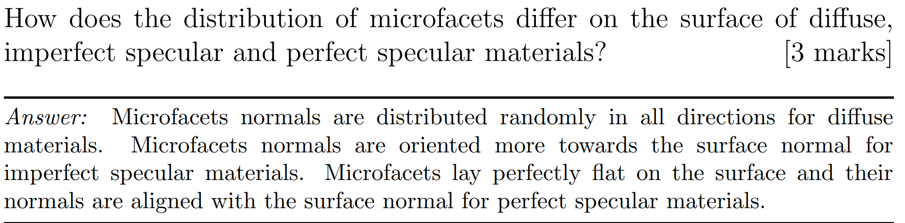
Imperfect specular reflection
In computer graphics, imperfect specular reflection is a technique used to simulate the way light is reflected off of an object’s surface in a more realistic manner. It is based on the idea that the reflection of light off of an object’s surface is not always perfect and that there are often small imperfections or irregularities that can affect the reflection.
The specular term models imperfect mirror-like reflection, in which the reflected light is distributed around the direction of reflection $R_i$. The paramter $K_s$ controls the amount of light that is reflected in a specular manner. The paramter $n$ models the shape of that distribution; high $n$ will result in tighter distribution and the behaviour that is closer to a perfect mirror light reflection. Scalar $I_i$ describes the intensity of the incoming light
Simulation
Anti-aliasing
Aliasing
Aliasing encompasses any effects attributable to discrete sampling
Spatial aliasing
- Jagged edge
- Missing small objects
- Broken thin objects
Temporal aliasing
- Counter-rotating discs
- Multiple images (when 25Hz updates are projected at 75 Hz)
Sampling
Assumed that each ray passes through the centre of a pixel
Leads to:
- stair step (jagged) edges to objects
- small objects being missed completely
- thin objects being missed completely or split into small pieces
Super-sampling
Shoot multiple rays through a pixel and average the result
Regular grid
- Divide the pixel into a number of sub-pixels and shoot a ray through the centre of each
- Problem: can still lead to noticeable aliasing unless a very high resolution sub-pixel grid is used
Random
- Shoot N rays at random points in the pixel
- Replaces aliasing artefacts with noise artefacts
- The eye is far less sensitive to noise than to aliasing
Jittered
- Divide the pixel into N sub-pixels and shoot one ray at a random point in each sub-pixel
- An approximation to Poisson disc sampling
- For N rays it is better than pure random sampling
- Easy to implement
Poisson disc
- Shoot N rays at random points in the pixel with proviso that no two rays shall pass through the pixel closer than $\varepsilon$ to one another
- For N rays this produces a better looking image than pure random sampling
- Very hard to implement properly
Adaptive super-sampling
- Shoot a few rays through the pixel, check the variance of the resulting values, if similar enough stop, otherwise shoot some more rays
Distributed ray tracing
Distributed ray tracing involves calculating multiple rays for each pixel with the sampling distributed over a range of parameter values
Distribute the rays going to a light source over some area
- Allows area light sources in addition to point and directional light sources
- Produces soft shadows with penumbrae
Distribute the camera position over some area
- Allows simulation of a camera with a finite aperture lens
- Produces depth of field effects
Distribute the samples in time
- Produces motion blur effects on any moving objects
- Temporal anti-aliasing
Graphics pipelining
Transformations
2D coordinates
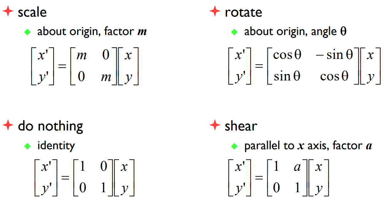
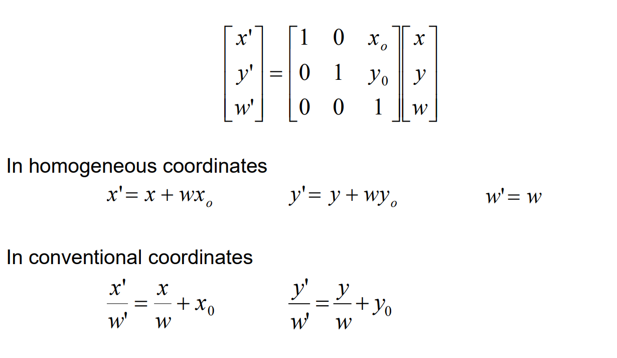
Homogeneous 2D coordinates
Translation by matrix algebra
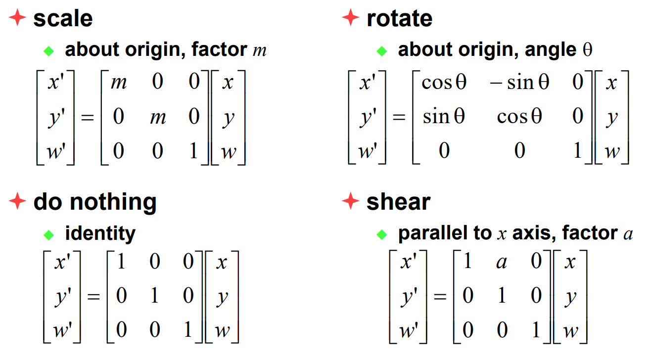
3D
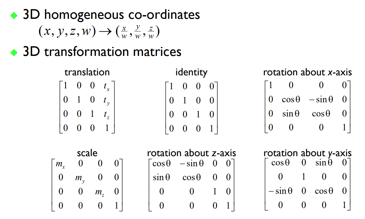
Projection - Matrix Operation
Order
- Scale
- Rotate
- Translate
Rasterization
- Model surfaces as polyhedra – meshes of polygons
- Use composition to build scenes
- Apply perspective transformation and project into plane of screen
- Work out which surface is closest
- Fill pixels with colour of nearest visible polygon
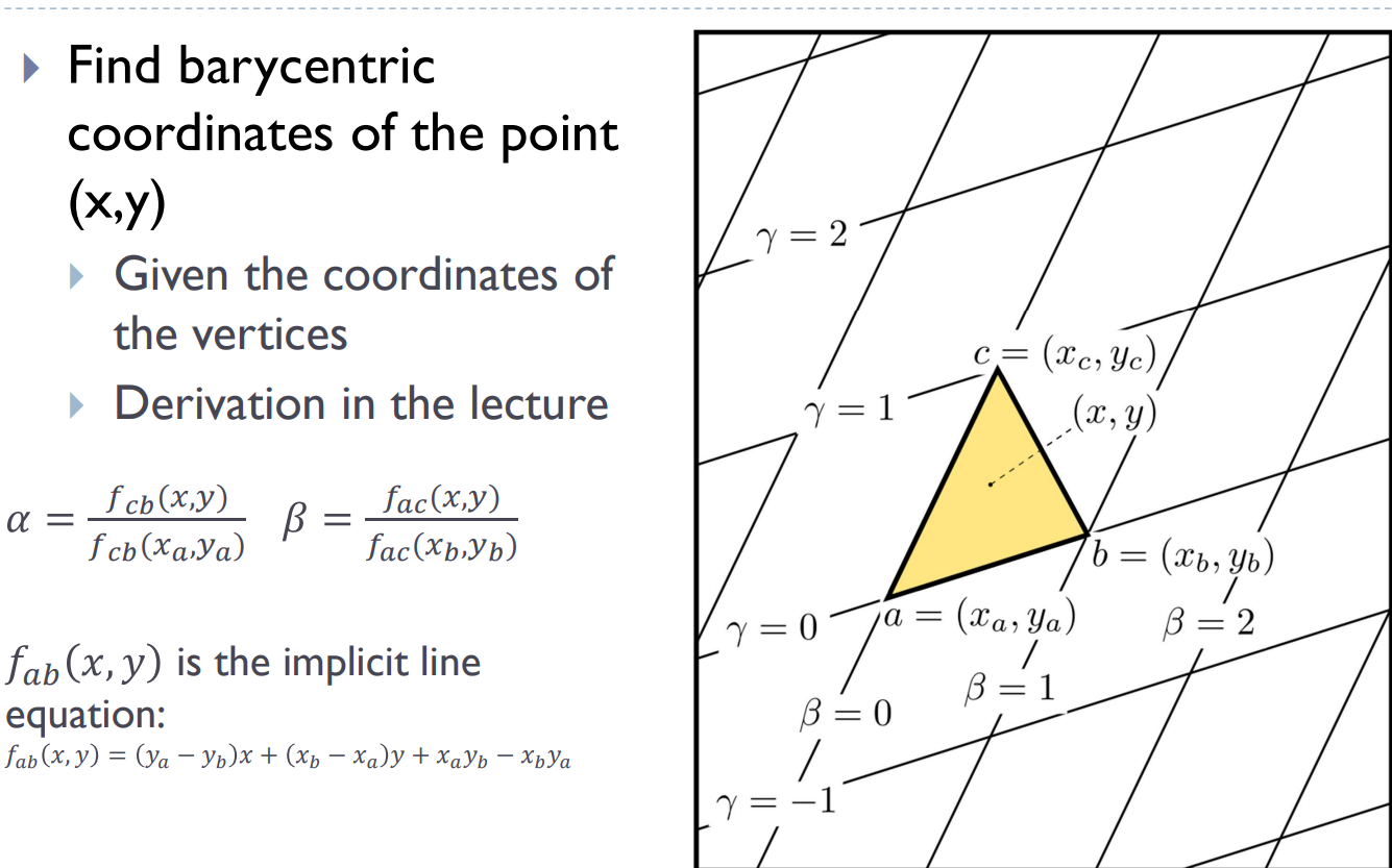
Homogenous barycentric coordinates
Used to interpolate colours, normals, texture coordinates, and other attributes inside the triangle
Triangle rasterization
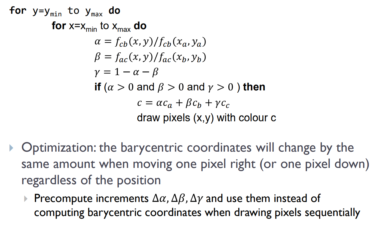
Z-Buffer Algorithm
1 | For every triangle in the scene do |
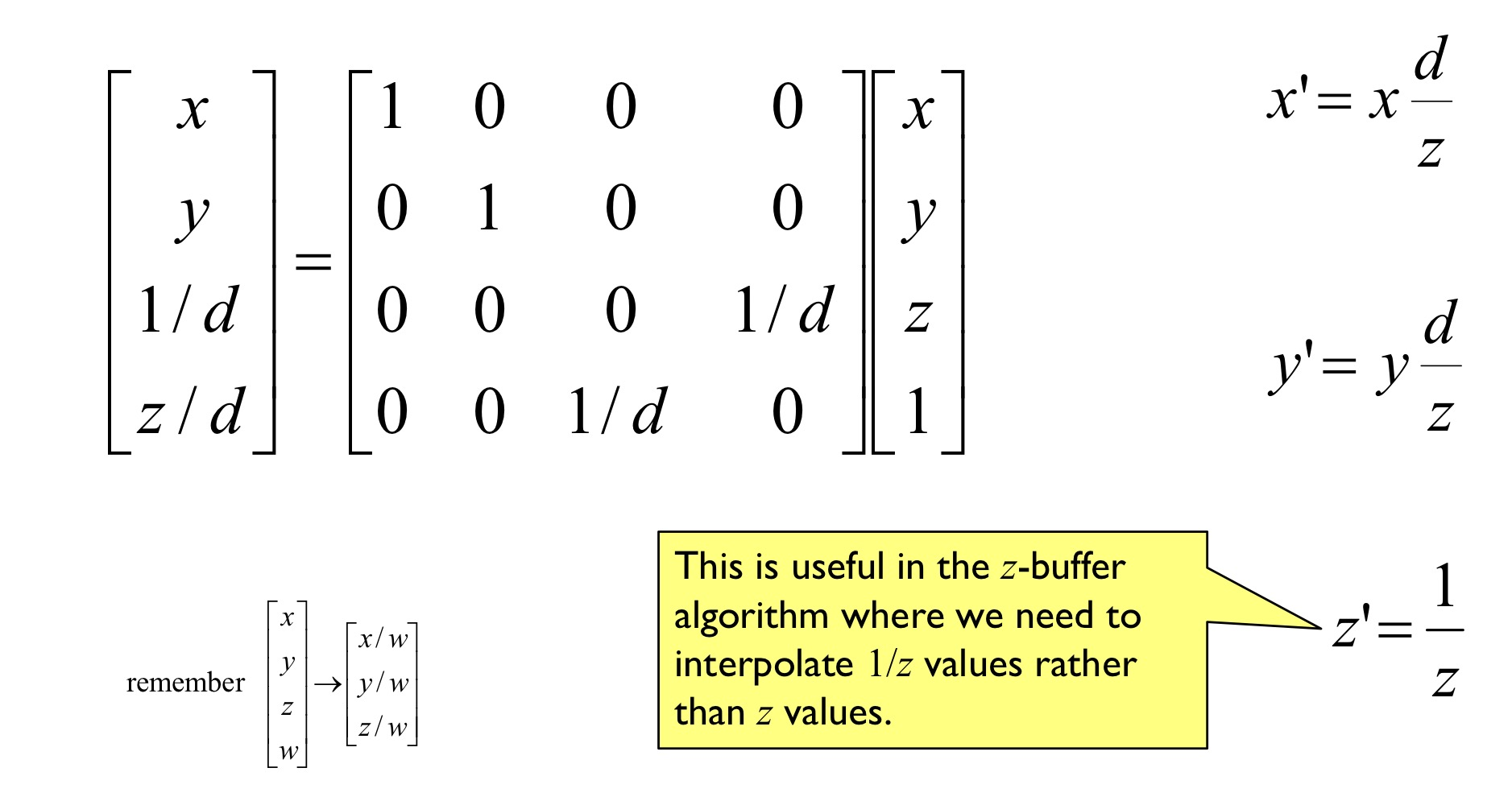
Z-buffer must store depth with sufficient precision
- 24 or 32 bit
- Integer or float
- Often 1/z instead of z
Graphics Hardware and modern OpenGL
OpenGL Rendering Pipeline
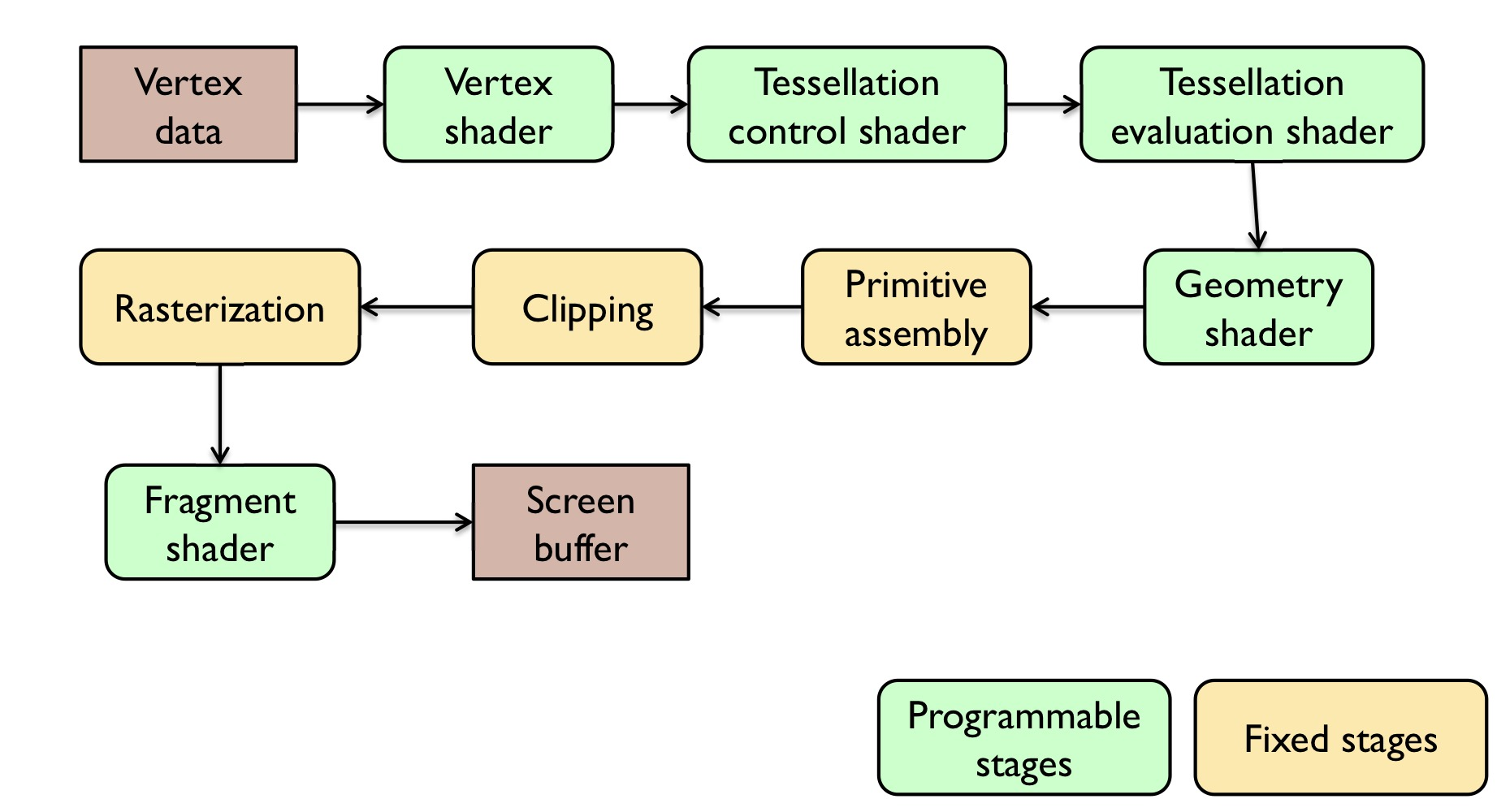
Vertex shader
Processing of vertices, normals, uv texture coordinates
Tessellation control shader + evaluation shader
[Optional] Create new primitives by tessellating existing primitives (patches).
Geometry shader
[Optional] Operate on tessellated geometry. Can create new primitives.
Primitive assembly
Organizes vertices into primitives and prepared them for rendering
Clipping
Remove or modify vertices so that they all lie within the viewport (view frustum)
Rasterization
Generates fragments(pixels) to be drawn for each primitive. Interpolated vertex attributes
Fragment shader
Computes colour per each fragment. Can lookup colour in the texture. Can modify pixels’ depth value.
Also used for tone mapping
Shaders
Shaders are small programs executed on a GPU
- Executed for each vertex, each pixel (fragment), etc.
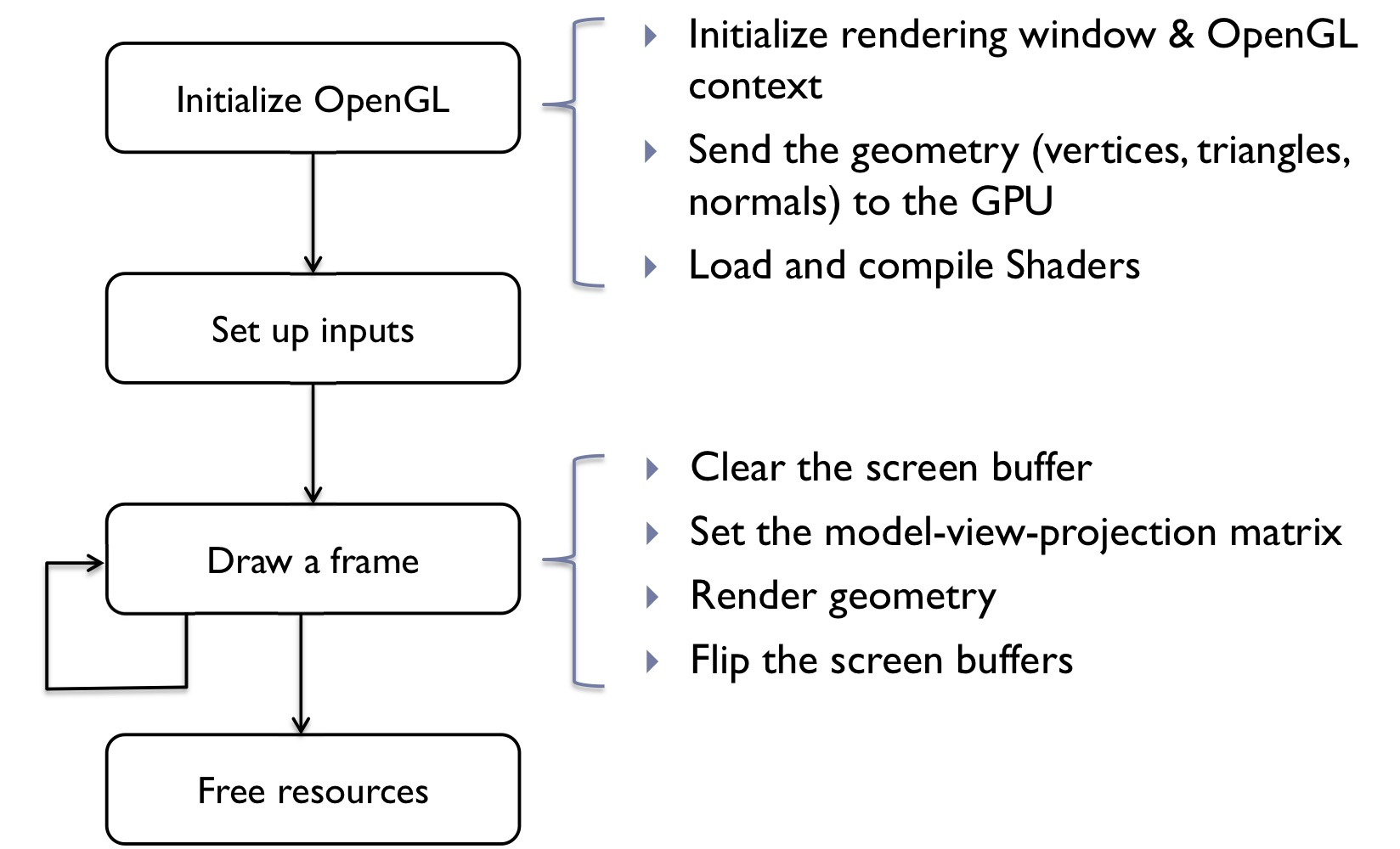
OpenGL Application flow
Textures
Up Sampling
When the texture resolution is insufficient for the rendered object, the values between texels needs to be interpolated. This operation is known as upsampling. OpenGL offers two interpolation filters:
Nearest-neighbour
Set interpolated values to the value of the nearest texel
Bi-linear interpolation
Interpolate values in a piece-wise linear manner for both horizontal and vertical dimensions
Down Sampling
When multiple texels are mapped to a single pixel, the values of these texels need to be averaged to avoid aliasing artefacts. The image processing operation of averaging and reducing resolution is known as downsampling. Because averaging texels for each drawn pixel could be very time-consuming, OpenGL often uses a pre-averaged values stored in a data structure called mip-map. A mip-map is a pyramid of textures, in which the resolution of each higher level is halved.
Bump (normal) mapping
- Special kind of texture that modifies surface normal
- The surface is still flat but the shading appears as on an uneven surface
- Easily done in fragment shader
Displacement mapping
- Texture that modifies surface
- Better results than bump mapping since the surface is not flat
- Requires geometry shader
Environment mapping
- To show environment reflected by the object
Environment cube
- Each face captures environment in that direction
Raster buffers (colour, depth, stencil)
Stencil Buffers
To block rendering selected pixels
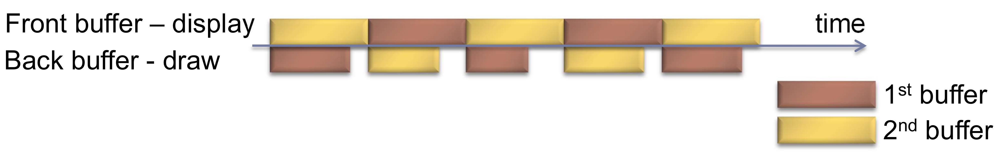
Double buffering
- To avoid flicker, tearing
- Use two buffers (raster)
- Front buffer - what is shown on the screen
- Back buffer - not shown, GPU draws into that buffer
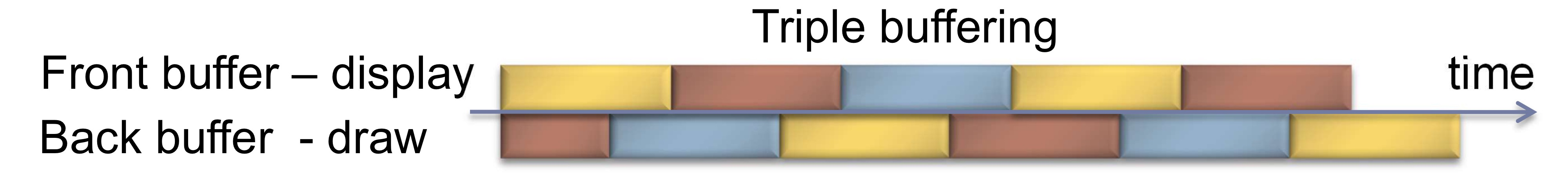
Triple buffering
- Do not wait for swapping to start drawing the next frame
- More memory needed
- Higher delay between drawing and displaying a frame
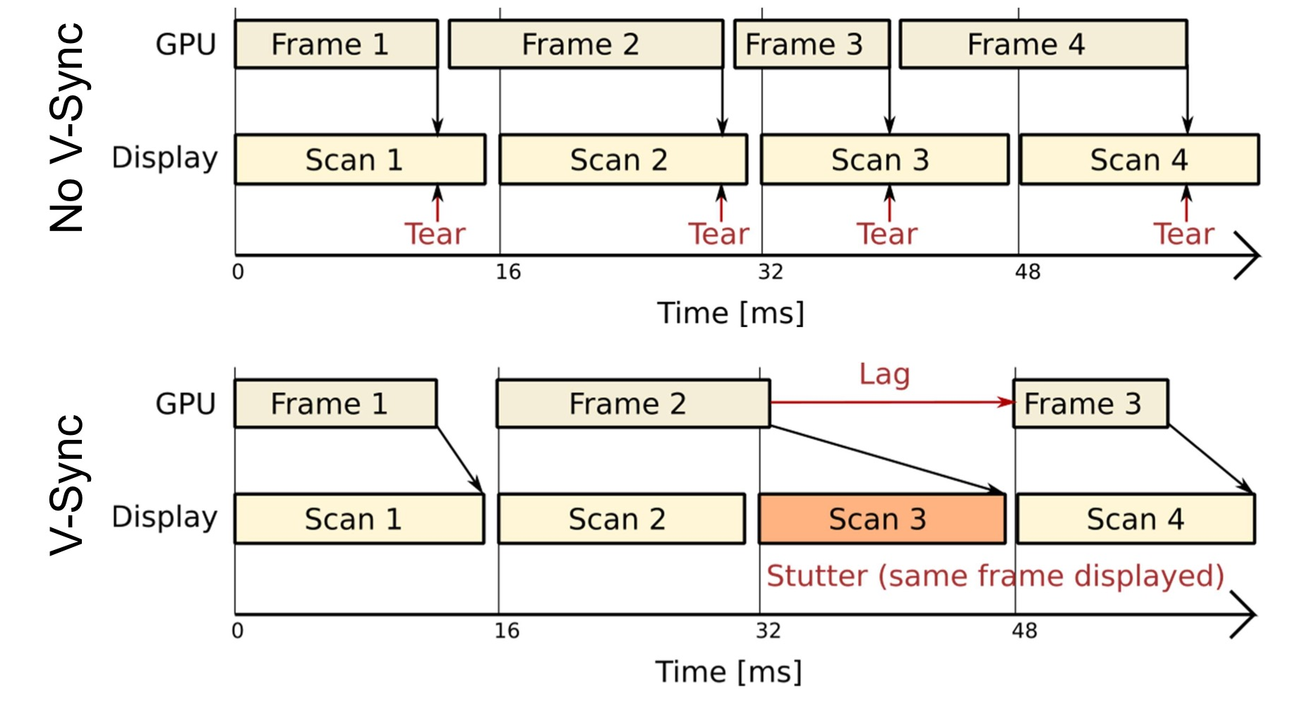
Vertical Synchronization: V-Sync
- Pixels are copied from colour buffer to monitor row-by-row
- If front & back buffer are swapped during thsi process
- Upper part of the screen contains previous frame
- Lower part of the screen contains current frame
- Result: tearing artefact
Solution: V-Sync
waits until the last row of pixels is copied to the display
FreeSync (AMD) & G-Sync (Nvidia)
Adaptive Sync
- Graphics card controls timing of the frames on the display
- Can save power for 30fps video of when the screen is static
- Can reduce lag for real-time graphics
Human vision, colour, and tone mapping
Structure of Human Eye
- Retina: an array of light detection cells
- Fovea: the high resolution area of retina
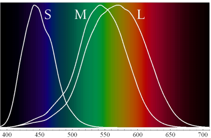
- Photoreceptors:
Cones: responsible for day-light vision and colour perception
- Three types of cones: sensitive to short(S), medium(M), and long(L) wavelengths
Rods: responsible for night-light vision
Colour
There is no physical definition of colour - colour is the result of our perception
For emissive displays/objects:
- Colour = Perception(spectral emission)
For reflective displays/objects:
- Colour = Perception(illumination * reflectance)
$L(\lambda)=I(\lambda)R(\lambda)$
Sensitivity Curves - Probability that a photon of that wavelengths will be absorbed by a photoreceptor.
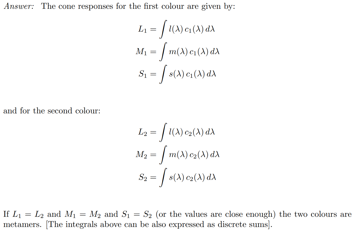
The light spectra that appear to have the same colour are called metamers
Noun: Metamerism
You are given spectra of two colours: c1(λ), c2(λ) and cone response functions l(λ), m(λ), s(λ). How would you test whether the colours c1 and c2 are metamers? Write down the equations for such a test
Tristimulus Colour Representation
Observation
- Any colour can be matched using three linear independent reference colours
- May require “negative” contribution to test colour
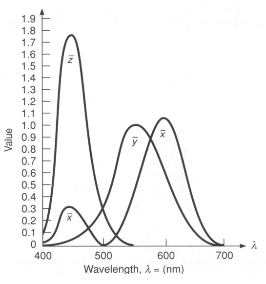
Standard Colour Space CIE XYZ
- 1931 Colour matching experiments
- Could match all physically realisable colour stimuli
- Cone sensitivity curve can be obtained by a linear transformation of CIE XYZ
- Y is roughly equivalent to luminance
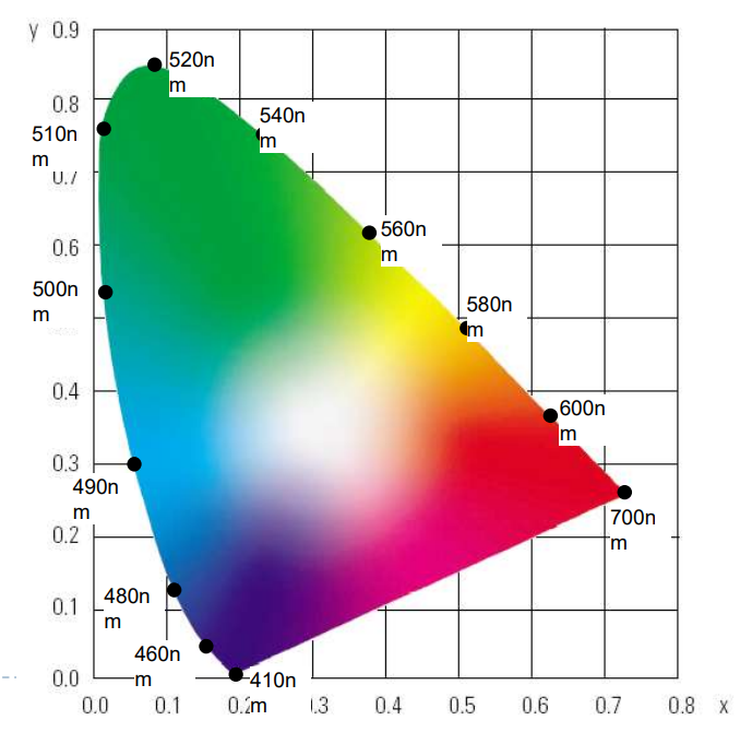
CIE chromaticity diagram
$x = X/(X+Y+Z),y= Y/(X+Y+Z),z= Z/(X+Y+Z)$
Achromatic/chromatic vision mechanism
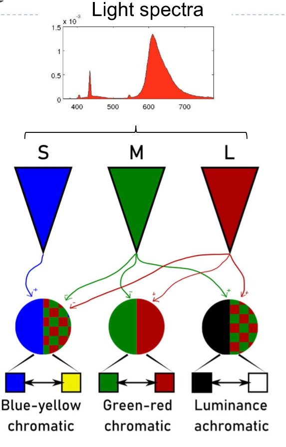
- M+L - Luminance achromatic (without colour)
- M+L - Green-red chromatic
- S+M+L - Blue-Yellow chromatic
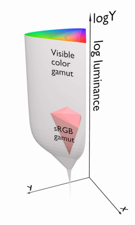
Visible/displayable colour
- All physically possible and visible colour form a solid in XYZ space
Each displayable device can produce a subspace of that solid
A chromaticity diagram is a slice taken from the 3D solid in XYZ space
Colour Gamut - the solid in a colour space
Usually defined in XYZ to be device-independent
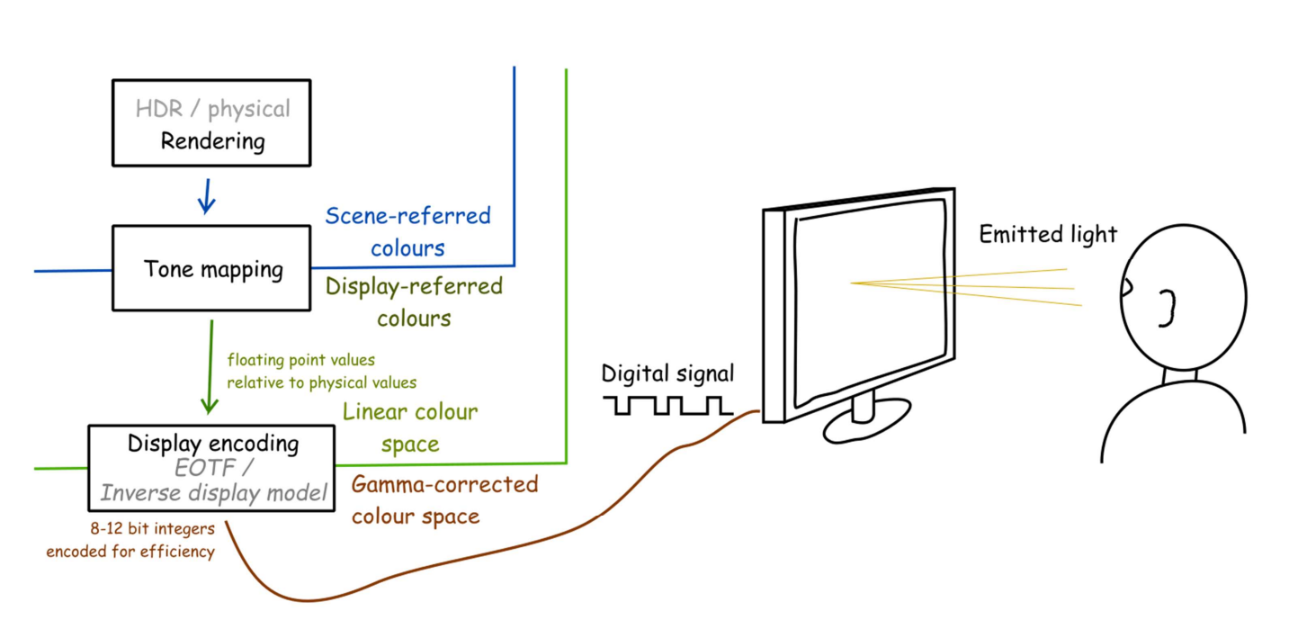
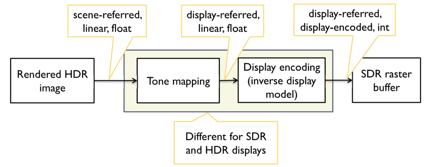
From rendering to display
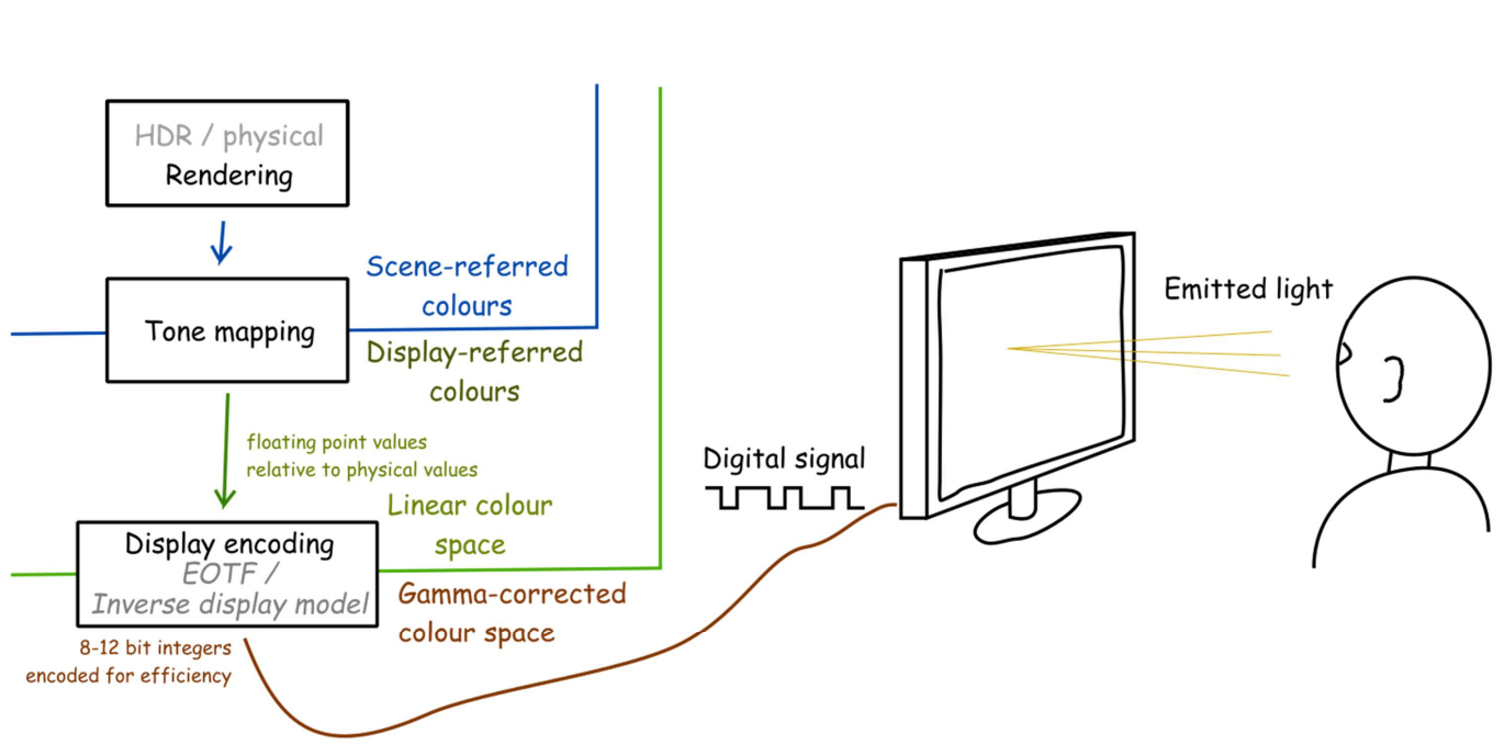
HDR / Physical rendering
- Scene-referred colours
Tone mapping
- Display-referred colours
- Floating-point values
Display encoding;EOTF(Electro-Optical transfer function) / Inverse display model
Gamma-corrected colour space
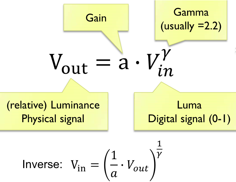
Gamma encoding of images is used to optimize the usage of bits when encoding an image, or bandwidth used to transport an image, by taking advantage of the non-linear manner in which humans perceive light and colour.
Gamma-corrected pixel values give a scale of brightness levels that is more perceptually uniform.
One of the main reasons for using gamma correction is to preserve the overall contrast of an image when it is displayed on different devices. Without gamma correction, an image that looks correct on one device may appear too dark or too light on another device, due to differences in the way the devices handle the brightness values of the pixels.
Gamma correction is also used to compensate for the fact that the human eye is more sensitive to light at certain wavelengths than at others. By encoding the brightness values in a way that takes this into account, the overall contrast and perceived brightness of an image can be more accurately reproduced on different devices.
8-12 bits integer encoded for efficiency
- 8-10bits for SDR
- 10-12bits for HDR
What is the purpose of mapping from scene-referred to display-referred colours:
The rendered scene-referred colours may exceed the dynamic range and colour gamut of the display. The mapping is performed to map the rendered colours to the gamut that can be reproduced on the target display
How does display encoding differ between standard and high-dynamic-range displays
Display encoding for SDR and HDR displays differ in the used colour spaces and transfer functions (display coding function). The colour space for HDR displays spans a larger colour gamut. The transfer function for HDR displays can encode a much larger range of colour values. Images that are display-encoded for HDR display have higher bit-depth(10-12bits) than those encoded for SDR displays (8-10 bits)

Representing colour
| Colour spaces | Linear and gamma corrected RGB, sRGB | HSV(Hue saturation value), HLS(Hue lightness saturation) | CIE Lab, CIE Luv | CMY Space |
|---|---|---|---|---|
| Features: | Can be quantised to small number of bits Can be linear(RGB) or display encoded (R’G’B’) Can be scene-referred(HDR) or display-referred(SDR) |
A set of numbers that are easy to interpret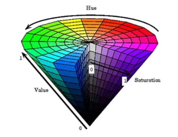 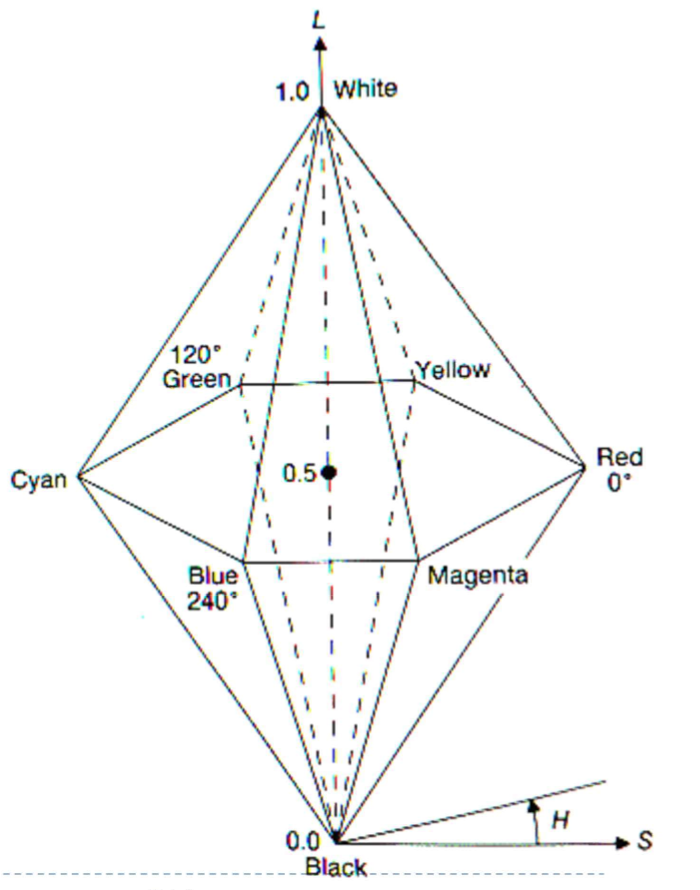 |
Perceptually uniform colour difference corresponded by the distance in the colour space | The important difference between CMY and RGB: Lights emit light, inks absorb light CMY is, at its simplest, the inverse of RGB |
| Applications: | Televisions, CRT monitors, LCD screens RGB is usually used to represent colours of emissive display devices. |
Colour pickers in the user-interface | Useful for computing colour differences or performing image processing operations | Printers: In real printing, CMYK (K refers to key, black) Because inks are not perfect absorbers Mixing CMY does not give us black Lots of text is printed in black |
| Colour Gamut | A cube | Complex | Complex |
Tone Mapping & Display Encoding
Why tone mapping?
- Reduce dynamic range
- Customize the look (colour grading)
- To simulate human vision
- To simulate a camera
- To adapt a displayed images to a display and viewing conditions
- Make the rendered image more realistic
- To map from scene to display-referred colour (primary purpose)
Explain how simulating glare that happens in the eyes or in a camera can enhance the appearance of rendered scenes.
- Rendered glare (or blooming) introduces the visual illusion that makes the sources of glare appear brighter than the maximum brightness of the display. It also makes the rendered scenes look more natural — closer to the look of perceived or camera-captured images.
Why is glare typically simulated only for the values that exceed the maximum displayable value?
- Glare is typically simulated only for the clipped/saturated values to avoid blurring of the rendered image. It is also done because the values reproduced on the display also cause glare in the eye and there is no need to simulate additional glare for those values.